A1360, A1361,
and A1362
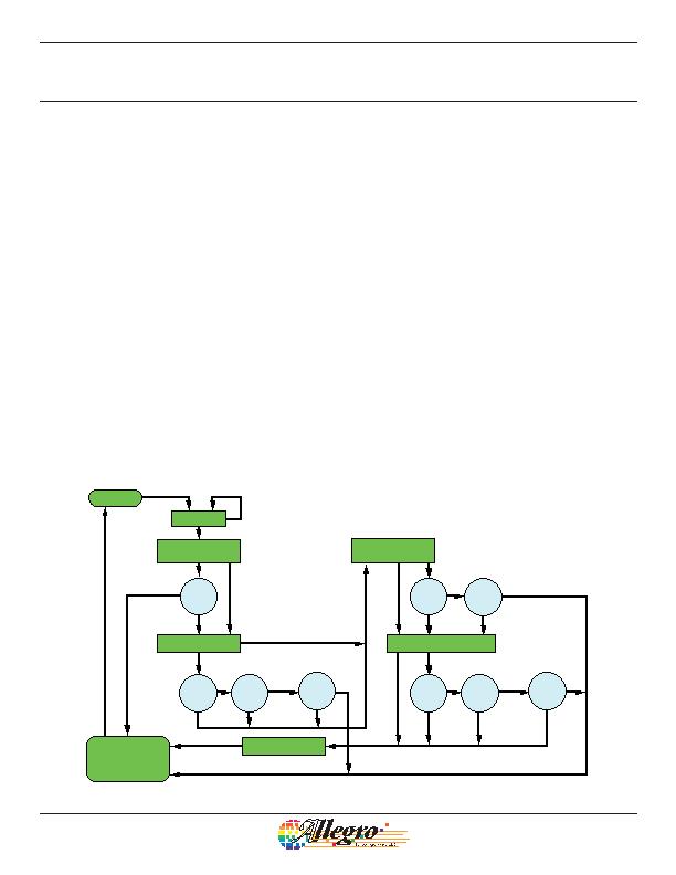
Programming State Machine
Initial State
After system power-up, the programming logic is reset to a
known state. This is referred to as the Initial state. All the bit field
locations that have intact fuses are set to logic 0. While in the Ini-
tial state, any V
PM
pulses on the VOUT pin are ignored. To enter
the zone 1 Parameter Selection state, apply a single V
PH
pulse on
VOUT pin. To enter the zone 2 Parameter Selection state, apply a
sequence of three V
PH
pulses on the VOUT pin.
Parameter Selection State
This state allows the selection of the parameter register contain-
ing the bit fields to be programmed. To select a parameter register
within the chosen zone, increment through the keys by sending
V
PM
pulses on the VOUT pin. Register keys select among the fol-
lowing programming parameters in zone 1:
1 pulse Sens,
and the following programming parameters in zone 2:
1 pulse V
OUT(Q)
2 pulses Coarse V
OUT(Q)
and LOCK
To enter the Bit Field Addressing state, send one V
PH
pulse on the
VOUT pin.
Note: When parameter selection for zone 1 is bypassed (by send-
ing a second V
PH
pulse) no register is selected, and V
PM
pulses
are ignored until after the V
PH
pulse is sent to enter zone 2.
Bit Field Addressing State
This state allows the selection of the individual bit fields to be
programmed in the selected parameter register (see the Program-
ming Logic table). To leave this state, either cycle device power
or blow the fuses for the selected code.
Note: Merely addressing the bit field does not permanently set
the value of the selected programming parameter; fuses must be
blown to do so.
Fuse Blowing State
To blow an addressed bit field, apply a V
PH
pulse on the VOUT
pin. Power to the device should then be cycled before additional
programming is attempted.
Note: Each bit representing a decimal code must be blown indi-
vidually (see the Fuse Blowing section).
Power-up
Initial
Parameter Selection
(Zone 1)
Parameter Selection
(Zone 2)
Bit Field Addressing
Sens
V
PH
V
PM
V
PH
V
PH
V
PH
V
PH
V
PH
V
PH
V
PH
V
PH
V
PM
V
PM
[Key sequence]
[Key sequence]
[Code sequence]
V
PM
V
PM
V
PM
V
PM
V
PM
V
PM
V
PM
V
PM
1
2
V
OUT(Q)
(Fine)
Coarse
V
OUT(Q)
or Lock
2
n
1
n= bits in
register
Bit Field Addressing
V
PH
V
PH
V
PH
V
PH
V
PH
[Code sequence]
V
PM
V
PM
V
PM
1
2
2
n
1
n= bits in
register
Fuse Blowing
User Power-down
Required
V
PM
= V
P(LOW)
?V
P(MID)
?V
P(LOW)
V
PH
= V
P(LOW)
?V
P(HIGH)
?V
P(LOW)
Low-Noise Programmable Linear Hall Effect Sensor ICs with
Adjustable Bandwidth (50 kHz Maximum) and Analog Output
20
Allegro MicroSystems, LLC
115 Northeast Cutoff
Worcester, Massachusetts 01615-0036 U.S.A.
1.508.853.5000; www.allegromicro.com
发布紧急采购,3分钟左右您将得到回复。
相关PDF资料
A1374EKB-T
IC SENSOR HALL EFFECT PREC 3-SIP
A1422LK
IC SENSOR HALL EFFECT AC 4-SIP
A1425LK
IC SENSOR HALL EFFECT AC 4-SIP
A1645LK-I2
IC SENSOR HALL EFFECT AC 4-SIP
A3230LUA-T
IC SW HALL EFFECT CHOPPER 3-SIP
A3241LUA-T
IC SWITCH HALL EFFECT 3-SIP
A3245LLHLT-T
IC SW HALL EFFECT OMNI SOT23W
A3251LUA-T
IC SW HALL EFFECT UNI 3-SIP
相关代理商/技术参数
A1362LKTTN-T
功能描述:IC HALL EFFECT SENSOR LN 4-SIP RoHS:是 类别:传感器,转换器 >> 磁性 - 霍尔效应,数字式开关,线性,罗盘 (IC) 系列:- 标准包装:1 系列:- 传感范围:20mT ~ 80mT 类型:旋转 电源电压:4.5 V ~ 5.5 V 电流 - 电源:15mA 电流 - 输出(最大):- 输出类型:数字式,PWM,8.5 位串行 特点:可编程 工作温度:-40°C ~ 150°C 封装/外壳:20-SSOP(0.209",5.30mm 宽) 供应商设备封装:20-SSOP 包装:Digi-Reel® 其它名称:AS5132-HSST-500DKR
A1363LKTTN-10-T
功能描述:IC HALL SENSOR 6.4-14MV/G 4SIP 制造商:allegro microsystems, llc 系列:- 包装:剪切带(CT) 零件状态:有效 类型:线性 技术:霍尔效应 轴:单路 感应范围:- 电压 - 电源:4.5 V ~ 5.5 V 电流 - 电源(最大值):15mA 电流 - 输出(最大值):10mA 输出类型:模拟电压 分辨率:- 带宽:120kHz 工作温度:-40°C ~ 150°C(TA) 特性:可编程,温度补偿 封装/外壳:4-SIP 模块 供应商器件封装:4-SIP 标准包装:1
A1363LKTTN-1-T
功能描述:IC HALL SENSOR 0.6-1.3MV/G 4SIP 制造商:allegro microsystems, llc 系列:- 包装:剪切带(CT) 零件状态:有效 类型:线性 技术:霍尔效应 轴:单路 感应范围:- 电压 - 电源:4.5 V ~ 5.5 V 电流 - 电源(最大值):15mA 电流 - 输出(最大值):10mA 输出类型:模拟电压 分辨率:- 带宽:120kHz 工作温度:-40°C ~ 150°C(TA) 特性:可编程,温度补偿 封装/外壳:4-SIP 模块 供应商器件封装:模块 标准包装:1
A1363LKTTN-2-T
功能描述:IC HALL SENSOR 1.3-2.9MV/G 4SIP 制造商:allegro microsystems, llc 系列:- 包装:剪切带(CT) 零件状态:有效 类型:线性 技术:霍尔效应 轴:单路 感应范围:- 电压 - 电源:4.5 V ~ 5.5 V 电流 - 电源(最大值):15mA 电流 - 输出(最大值):10mA 输出类型:模拟电压 分辨率:- 带宽:120kHz 工作温度:-40°C ~ 150°C(TA) 特性:可编程,温度补偿 封装/外壳:4-SIP 模块 供应商器件封装:4-SIP 标准包装:1
A1363LKTTN-5-T
功能描述:IC HALL SENSOR 2.9-6.4MV/G 4SIP 制造商:allegro microsystems, llc 系列:- 包装:剪切带(CT) 零件状态:有效 类型:线性 技术:霍尔效应 轴:单路 感应范围:- 电压 - 电源:4.5 V ~ 5.5 V 电流 - 电源(最大值):15mA 电流 - 输出(最大值):10mA 输出类型:模拟电压 分辨率:- 带宽:120kHz 工作温度:-40°C ~ 150°C(TA) 特性:可编程,温度补偿 封装/外壳:4-SIP 模块 供应商器件封装:4-SIP 标准包装:1
A1363LLUTR-10-T
功能描述:IC HALL EFFECT SENSOR LN 8TSSOP 制造商:allegro microsystems, llc 系列:- 包装:剪切带(CT) 零件状态:有效 类型:线性 技术:霍尔效应 轴:单路 感应范围:- 电压 - 电源:4.5 V ~ 5.5 V 电流 - 电源(最大值):15mA 电流 - 输出(最大值):10mA 输出类型:模拟电压 分辨率:- 带宽:120kHz 工作温度:-40°C ~ 150°C(TA) 特性:可编程,温度补偿 封装/外壳:8-TSSOP(0.173",4.40mm 宽) 供应商器件封装:8-TSSOP 标准包装:1
A1363LLUTR-1-T
功能描述:IC HALL EFFECT SENSOR LN 8TSSOP 制造商:allegro microsystems, llc 系列:- 包装:剪切带(CT) 零件状态:有效 类型:线性 技术:霍尔效应 轴:单路 感应范围:- 电压 - 电源:4.5 V ~ 5.5 V 电流 - 电源(最大值):15mA 电流 - 输出(最大值):10mA 输出类型:模拟电压 分辨率:- 带宽:120kHz 工作温度:-40°C ~ 150°C(TA) 特性:可编程,温度补偿 封装/外壳:8-TSSOP(0.173",4.40mm 宽) 供应商器件封装:8-TSSOP 标准包装:1
A1363LLUTR-2-T
功能描述:IC HALL EFFECT SENSOR LN 8TSSOP 制造商:allegro microsystems, llc 系列:- 包装:剪切带(CT) 零件状态:有效 类型:线性 技术:霍尔效应 轴:单路 感应范围:- 电压 - 电源:4.5 V ~ 5.5 V 电流 - 电源(最大值):15mA 电流 - 输出(最大值):10mA 输出类型:模拟电压 分辨率:- 带宽:120kHz 工作温度:-40°C ~ 150°C(TA) 特性:可编程,温度补偿 封装/外壳:8-TSSOP(0.173",4.40mm 宽) 供应商器件封装:8-TSSOP 标准包装:1